
Reasons and Solutions for Dimensional Deviations in CNC Lathe Machining
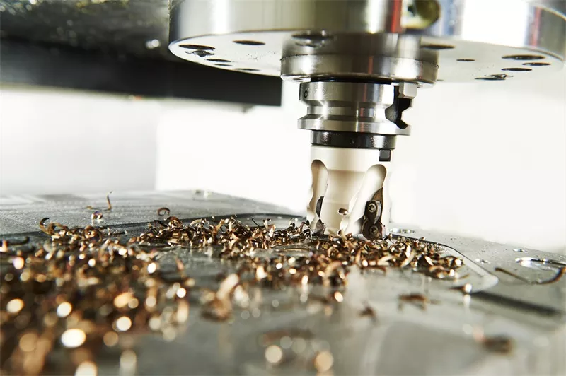
We should all know that CNC lathes are equipped with control devices such as CNC numerical control systems and servo control systems, as well as executive mechanisms like high-precision feed systems and tool magazines. It is these components that form a new type of processing equipment. In terms of processing form, its processing method is quite different from any other type of machining machine tool. To put it simply, CNC lathes are an integrated, high-efficiency, and high-precision machining equipment that combines automated machining and composite centralized machining. However, there are many reasons that affect the precision and processing efficiency of CNC lathe workpieces. Below, we will briefly introduce the causes of dimensional deviations in CNC lathe workpieces and the corresponding solutions, for users' reference only.
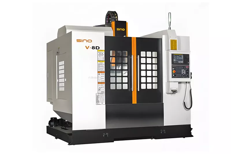
To understand the causes of workpiece size deviation during machining, we first need to be clear about the composition of CNC lathes. CNC lathes are mainly composed of a control system, servo drive unit, mechanical feed mechanism, servo motor, worktable position, and feedback measurement device. When machining a workpiece, first, after digital calculations by the CNC system, control signals are sent to the servo drive unit. Then, the servo motor is driven to rotate, and the motion is transmitted to the worktable through the mechanical feed mechanism, causing relative movement between the workpiece and the tool. At the same time, the position detection and feedback device converts the actual relative displacement between the workpiece and the tool into an electrical signal, which is then fed back to the CNC unit. The CNC unit compares the commanded displacement with the actual feedback displacement, thereby machining a workpiece that meets the design requirements of the machining program. However, in the actual machining of workpieces on CNC lathes, it often happens that the workpiece and tool do not move relatively according to the command value, leading to the machined part's dimensions not matching the design. This results in size deviation of the machined workpiece. Usually, the causes of such faults are as follows:
1.The actual positioning value of the servo motor does not match the command positioning value, resulting in dimensional deviation of the machined workpiece.
2. The actual position value of the servo motor matches the command position value, but the actual relative movement between the workpiece and the tool during machining does not meet the corresponding requirements.
3. The zero position of the feed system of the CNC lathe has a deviation.
4. Pulse loss, external interference, or mechanical failures causing deviations in the machined workpiece.
The specific solutions for solving the dimensional deviation of workpieces processed by CNC lathes are as follows:
CNC lathes are typically equipped with electronic control devices that include CNC systems and servo control systems. Such systems usually have error compensation functions, so using software compensation is the most effective and direct method to prevent and resolve deviations in the dimensions of machined workpieces. This mainly includes two methods: tool compensation and interpolation algorithms, as specifically described below:
1.Method of compensation using tools
The tool compensation method is primarily used to compensate for the tool, preventing excessive dimensional deviations in workpieces during CNC lathe machining. This method is commonly used and effective. However, when performing tool compensation, it is first necessary to determine the type of transition between the trajectories of the two preceding and following program segments. For transitions between arcs and lines, there are four types of connections: line-to-line, line-to-arc, arc-to-line, and arc-to-arc. Depending on the vector angle between the two program trajectory segments and the direction of the tool compensation, the tool radius compensation for the program segment transition can be categorized into three types of connection methods: shortened, extended, and inserted.
2. Method of compensation using interpolation algorithms
The numerical control system of a CNC lathe can only use the start and end coordinate values of a trajectory as data values. Therefore, data point densification needs to be performed between the start and end points. This process is also called interpolation. Through this interpolation process, the tool's cutting motion trajectory during the entire machining process can be controlled in real time, significantly reducing the impact caused by some unforeseen factors leading to excessive workpiece machining dimensions, thereby achieving high-precision machining of the workpiece.